The Journey of a Thousand Miles Begins With a Single CutThe first look at a beginner's journey into woodworking with a ShopSmith. Continue Reading
Workbench: It works if you work it (and build it)!!Building a wall-mounted workbench (with modifications) to fit a one-car garage shop. Continue Reading
Custom-Built ShopSmith-Mounted CabinetA three-part series about building and mounting an under-ShopSmith storage cabinet. Continue Reading
It has been several months since my last post, and I feel pretty bad about not providing any updates, much less videos, in the last few months. Life, and then weather, unfortunately happened.
As some of you may have seen, my new video went up today!
While there's not much going on in the video, it represents the first major step in my shop redesign!
I work in an uninsulated one-car garage here in the Phoenix valley, and as the summers keep getting hotter, it's more important than ever for me to find ways to maximize my efficiency, as my available working time gets shorter. The layout I had previously was crowded, and required a lot of moving things around in order to change work functions. I just don't have time for that! I've been looking through articles, blog posts, videos, and more just to try to garner some ideas of how to work effectively within the confines of my shop.
About a year ago, I stumbled across this article from Fine Woodworking about the Smart Shop in a One-Car Garage. It's an older post, but it happens that this just about perfectly matches the dimensions of my work space. There are some changes that I needed to make, as I don't have the resources to drop new electrical lines into the garage, nor do I have an open ceiling allowing for overhead lumber storage.
Also around this time, Wood Magazine was finishing up their Idea Shop 6 series. Between these two resources, I was able to piece together a good plan of attack for my place!
I've started by replacing my old lumber rack. This beast was fantastic, but really took up all the best real-estate on that wall.
The Behemoth!
By moving to this new design, I've freed up a lot of floor and wall space.
Loaded up!
Wall detail
It's not really clear, but I now have about five feet of usable wall space below the new racks. The downside is that I don't have dedicated storage for sheet goods in the shop any more. However, I happen to have an amazing wife who allowed me to move the old rack into our two-car garage (that we actually use to park the cars in!). This lets me store sheet goods, and lumber for upcoming projects that still needs to reach equilibrium. Ideally, I will have material for active and next project on the rack in the shop, and material for the next two to three projects in the garage. We'll see if I can stick to that!
That's about all for this post. The next major project is going to be a table system for my radial arm saw. With luck, that'll be done in a couple of weeks!
Time got away from me last Sunday, and didn't make it out to the shop again until today. It's probably a good thing as the tapering jig ended up posing a lot of difficulty, and it alone is nearly an article in and of itself. Today I made the adjustable stop and the tapering jig, which primarily used rip and cross cuts to complete.
Adjustable stop
Tapering jig
Once again the voice activation on my phone's camera was acting up again, so I didn't get as many pictures as I would like. I get into a flow when I'm working, and forget to move over to the tripod and snap a shot, or I forget to move the tripod entirely and it's in completely the wrong location. I'm pondering some different options to bypass this difficulty, but it will be a little bit before I'm able to do anything with them. Soon!
Adjustable Stop
The adjustable stop is made from 2x4 and 3/4" ply wood. I "milled" the 2x4 on the
table saw, and it's pretty darn close to square. John Heisz has a
really great video demonstrating a good way to do this. He also has a much more in depth article about the process.
After cutting the side pieces, I placed them loosely to either side of the
fence and measured across to determine the length of the top. Since I
have the 520 Pro Fence, the dimensions given in Power Tool Woodworking
For Everyone don't work, as they are for much smaller fences. I
ripped some scrap plywood to width, then cut it down to about 5 inches.
Cross cutting the side pieces
Pretty good!
Taking measurements for the top piece
Ripping some plywood to width for the top
Cross cutting to length
I drilled pilot holes for the screws, and then laid out
the marks for the threaded T-nut, and used a 1/2" spade bit to drill it
out. I hammered the T-nut into place, and used some scrap wood and
c-clamps to finish pressing it down nearly flush with the wood.
Pilot holes drilled, now preparing to drill for the threaded T-nut
Hammer it home!
Hammered into place
Top attached with screws only
Then it was a simple matter of screwing the top on to the sides, and threading in the eye-bolt.
Locking eye-bolt threaded into T-nut
In position!
Tapering Jig
Next I moved my attention to the tapering jig. I originally planned to use plywood for this jig, but all of my scrap of sufficient size are slightly bowed. A couple of weeks ago, I got some really nice hard country maple, and thought I'd use that instead. I only have a small amount, so I ripped and cross cut the two smallest boards. They were somewhat rough, and one of them was slightly bowed, so I thought I'd try out my jointer. This was an utter failure. I'm going to have to read up on jointer functionality and dealing with slightly bowed stock. I should have stuck with the table saw method.
The piece that was sad
I'll be able to salvage some usable stock from this, but it was not suitable for the jig with the skills and tools I have available. I dug deep and managed to find a piece of plywood that was in good enough shape, so I used that instead.
I ripped the stock to width, then cross cut to length.
Ripping to width
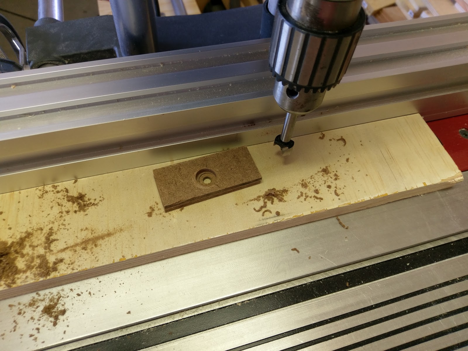
There wasn't much cutting for this project. Mostly it was hardware. After cutting the arms, I cut the stop block to size, drilled a 1/4" inch hole through it with a 5/8" counter sink on the bottom to accept the carriage bolt, then glued it to one of the arms taking care to keep it flush with the back edge.
Gluing stop block into place
After the glue dried, I laid the arms end-to-end and positioned the hinge. I marked the screw positions, and carefully drilled pilot holes, and screwed the hinge in place. Self-centering bits are definitely a purchase I will make soon!
Hinge placement
The cross-tie is made from a small piece of 1/2" plywood that I found in the scrap bin. Using the plans, I measured and marked a 12"x2" blank for all the cuts and holes. I used a 1/4" bit to drill the two end holes of the slot, drew some connecting lines, and cut out the rest of the waste with my jig-saw. I cleaned it up as best as I could with a file, but it's a bit rough. It works fine, though, so that's good enough for a shop jig! I then set up the bandsaw and cut the tapers...for the tapering jig...Mhm.
Cross tie in place
I measured 12" down from the hinge end, and made a square mark across both arms, made corresponding marks on the cross-tie at the 1:12, 2:12, 3:12 points. At full extension, this jig cuts a taper at just under 3.75":12". It is also much larger than I thought it would be!
Set up at a 3":12" taper
Marks at the 12" point for calibration
In the process of making this jig, I made an unfortunate discovery regarding my cabinet. While preparing the stop, I needed to bore a 1/4" hole through the center of the wood. I was going to use the horizontal boring function, but much to my chagrin, the cabinet top stops the table's support tubes from descending far enough to position the table below the level of the drill chuck. I will have to make some adjustments.
After all is said and done, though, it was a productive day. I have now finished the 4 jigs that I thought would showcase the skills that I learned in the first five assignments of lesson 1!
I was considering going through all of the assignments in all of the lessons back to back, and posting them consecutively before moving on to any projects. On further consideration (and the wife's input), I've determined that this would likely get boring quickly. Not just for me, but also for you, dear readers! Therefore, I will be going back and forth between skill learning with the assignments in the self-study course, and practical application by making jigs and fixtures from Power Tool Woodworking For Everyone.
This week I looked at tackling two different miter gauge extensions.
Both of these projects use, almost exclusively, the skills I learned and practiced last week.
Unfortunately, I ran into a snag right off the bat. On Thursday, I finally remembered that I had read on the ShopSmith forums how to fix the orientation of my quill depth dial. However, upon loosening the setscrew on the spring housing, the tensioning spring unwound. I didn't think this was a big deal at the time, as re-tensioning the spring takes just a few minutes. What I didn't know, and found out this morning upon attempting the process, was the that spring had slipped off of the internal pin, and wasn't re-engaging. I ended up spending almost two hours disassembling the quill feed mechanism, reattaching the spring to the internal pin, then wrestling with that sub-assembly to get it back into the spring housing.
By this time, it was starting to get pretty warm in the shop, and the voice actuator on my camera decided to not work today, so I didn't get as many pictures as I would have liked.
Adjustable Miter Gauge Extension
This is a pretty simple fixture. I cut down a piece of 3/4" plywood to 3"x15". Then, using a router, I made a 1/4" wide slot with a 5/8" counter-sunk groove running through the middle of the length that is about 1" from each end.
Set the fence for 3" from inside tooth
Rip to width. Push sticks are your friend!
As you can see in the final picture, the carriage bolts are recessed from the face of the miter gauge extension, and it can be easily moved across nearly it's entire length. I like to bring it right up the edge of the blade, so I know exactly where to position my cut line.
Miter Gauge Extension with Sliding Stop
This one took a lot more time than the other gauge, but I really like it! This thing is a beast! It's thicker than it should be, as re-sawing plywood is not particularly pretty, and it's tough to joint/plane afterwards. So I didn't. It's just under 1.5" think (two layers of 3/4" plywood), but it used every technique I learned last week, which is pretty cool! I ripped some plywood down to 3" for the back, and two pieces 1.25" for the front track. I then cross cut each one down to 23". The two front pieces had a 0.25" x 0.25" rabbet ripped along one edge. The stop had a 0.25" x 1.25" rabbet cut onto each side. 1/4" holes with 5/8" countersinks were driven in the rear board, and two small 5/8" cut-outs were made in the front to accommodate the carriage bolts. The whole thing was then glued up and later assembled.
Cross cutting rear section
Setting up to rip the front pieces
Gluing up the main assembly
Gluing up the sliding stop, I doubled up two pieces of 1/8" hardboard for the internal portion.
Drilling and counter sinking
Assembling the stop
Stop installed in the main assembly
Installed on the miter gauge. This thing is massive!
All-in-all, this was a good day in the shop. It started out with a lot of frustration, but I did learn a bit more about my machine, which is cool. I also finally got my quill depth gauge set up so that I can actually use it without guesswork! The miter gauge extensions are going to help out tremendously with future projects, and I've been wanting something more substantial than the little 12" extension that came with my machine. I now have two very useful alternatives!